A flawless shadow gap relies not on the profile you choose, but on the precise coordination between the dryliner’s boarding sequence and the electrician’s cabling.
- Thermal expansion between aluminum and gypsum is the primary cause of cracking, requiring reinforced junctions.
- The “dotting effect” is solved by strictly adhering to depth-to-pitch ratios and utilizing COB technology.
Recommendation: Prioritize plaster-in profiles with a minimum 1:1 depth ratio and install them strictly during the boarding phase, not after.
The “floating ceiling” is perhaps the most requested feature in contemporary minimalist renovations, yet it remains one of the most difficult details to execute perfectly. For architects and renovations professionals, the challenge is rarely the concept itself, but the harsh reality of physics. A shadow gap acts as a deliberate disconnection between wall and ceiling, but if engineered poorly, it becomes a magnet for hairline cracks and visible tape seams.
While standard advice often suggests simply “buying a good LED channel,” the reality of a site environment is far more unforgiving. We are dealing with the collision of two disparate materials—aluminum extrusions and gypsum plaster—expanding and contracting at different rates under the thermal load of high-output LEDs. Beyond the structural integrity, there is the aesthetic pitfall of the “dotting effect,” where a sophisticated linear light is reduced to a cheap-looking string of Christmas lights.
But if we shift our focus from the product to the integration process, we can achieve that seamless, architectural glow. By understanding the thermal mechanics and the critical path of installation, we can design details that remain pristine for years. This guide explores the technical intersection of light and plaster to deliver a truly floating effect.
To navigate the complexities of this architectural detail, the following breakdown covers every critical junction from framing to finish.
Table of Contents: Designing the Perfect Shadow Gap
- Why Shadow Gaps Crack and How to Reinforce Them
- How to Position LED Tape to Avoid Dotting Effects
- Plaster-In vs Surface Mount Channels: Is the Mess Worth It?
- The Driver Location Mistake That Requires Ceiling Demolition
- When to Install Lighting Channels: Before or After Boarding?
- How to Install Shadow Gap Skirting for a Contemporary Finish
- Hidden Beam vs Box Frame: Which Maximizes Ceiling Height?
- Removing Load-Bearing Walls: Costs and Regulations in the UK
Why Shadow Gaps Crack and How to Reinforce Them
Shadow gaps crack primarily because aluminum profiles and gypsum board have significantly different coefficients of thermal expansion, causing movement at the feathering edge when the LEDs heat up. This is not a failure of the plaster, but a failure of the junction design. When high-wattage LED tape generates heat, the aluminum channel expands; if the bond with the plaster is rigid and unreinforced, that energy releases as a hairline fracture.
To mitigate this, the structural integrity of the sub-frame is paramount. A floating ceiling creates a cantilevered load at the perimeter. If the timber or metal framework has any flex, vibration from footfall on the floor above will inevitably transmit to the delicate plaster edge of the shadow gap. The profile itself must be treated not just as a trim, but as a structural component that requires rigid mechanical fixing.
Furthermore, the chemical bond is just as vital as the mechanical one. The anodized surface of an aluminum profile is non-porous, making it difficult for standard gypsum skim to adhere long-term without a primer or a dedicated mesh wing. The goal is to create a monolithic union where the profile and the board move as one unit.
Ultimately, a crack-free finish is the baseline for success, but the quality of the illumination is what defines the architecture.
How to Position LED Tape to Avoid Dotting Effects
To position LED tape effectively and avoid the “dotting effect,” you must strictly adhere to a depth-to-pitch ratio where the distance from the LED chip to the diffuser is at least equal to the distance between the chips. If the profile is too shallow or the LEDs are spaced too far apart, the individual points of light will not overlap sufficiently before hitting the diffuser, resulting in a spotted, unrefined look rather than a continuous bar of light.
This phenomenon is the quickest way to devalue a minimalist interior. To solve this, lighting designers prioritize the depth-to-pitch ratio. For standard SMD (Surface Mounted Device) strips, the channel depth is critical. However, newer technology allows for shallower installations without compromising the effect. The macro photograph below highlights the stark difference in texture and continuity between standard and optimized solutions.
As illustrated, the seamless output on the right is achieved not just by diffusion, but by the density of the light source. This is where Chip on Board (COB) technology becomes indispensable for shallow architectural details. By packing hundreds of chips directly onto the circuit board, the “pitch” becomes negligible.
Ideally, you should aim for a 1:1 minimum depth-to-pitch ratio required according to professional LED profile guidelines to ensure a spotless finish. The table below compares the two dominant technologies available for these applications.
To further understand the trade-offs between these technologies, consider this direct comparison provided by a comprehensive analysis of strip types.
| Feature | COB LED Strip | SMD LED Strip |
|---|---|---|
| Light Output | Uniform, dot-free illumination | Visible hotspots without diffusion |
| Beam Angle | Up to 180 degrees | 120 degrees typical |
| Heat Dissipation | Evenly spread thermal load | Concentrated hot zones at each chip |
| Energy Efficiency | Higher efficiency | Uses more energy for comparable output |
| Flexibility | Highly flexible, fits tight spaces | Slightly bulkier |
| Cost | Higher upfront cost | More budget-friendly |
| Ideal Application | Shallow shadow gaps, exposed installations | Deep profiles with heavy diffusion |
Choosing the right LED engine is only half the battle; how that engine is housed within the ceiling plane determines the longevity of the installation.
Plaster-In vs Surface Mount Channels: Is the Mess Worth It?
The mess of a plaster-in installation is absolutely worth it for minimalist projects because it allows the aluminum channel to act as a heat sink integrated into the building fabric, significantly extending LED lifespan while removing visual clutter. While surface-mounted profiles are easier to install, they disrupt the plane of the ceiling and fail to provide the “disappearing” edge that characterizes a true shadow gap.
A plaster-in profile features perforated wings that are skimmed over, effectively burying the hardware. This requires a much higher level of skill from the plasterer—specifically a “Level 5” finish—to feather the compound out so the ceiling remains perfectly flat. The visual payoff is a line of light that appears to be cut directly into the architecture.
Case Study: The Integration Imperative
LED Profilelement installations demonstrate that many plaster-in profiles feature either a plaster-in design or paintable wing for seamless integration into architectural schemes. These systems are installed directly into drywall, taking advantage of the latest LED innovations while achieving the invisible finish that minimalist design demands—but require Level 5 plastering skills to execute flawlessly.
However, the permanence of this solution introduces a risk: maintenance. Unlike surface-mounted channels that can be unscrewed, a plaster-in channel is part of the wall. If the LED strip fails, you can usually pull it out from the front, but if the channel itself is damaged, it requires demolition. Therefore, the durability of the anodized finish and the quality of the diffuser cover are non-negotiable specifications.
The permanence of plaster-in channels means that any component buried behind them is effectively gone forever, which brings us to the critical issue of drivers.
The Driver Location Mistake That Requires Ceiling Demolition
The most catastrophic mistake in shadow gap lighting is placing the LED driver (power supply) inside the ceiling void behind a plastered-in profile without an access hatch. Drivers are electronic components with a finite lifespan, typically shorter than the LED tape itself. If a driver fails and is sealed inside a “floating” ceiling, the only way to replace it is to destroy the plasterwork you labored to perfect.
The professional approach is to locate all drivers remotely, such as in a utility cupboard or a ventilated joinery unit. This creates a new challenge: voltage drop. Low voltage DC power (12V or 24V) loses strength over long cable runs. If the wire is too thin or the run too long, the LEDs will appear dim or inconsistent.
To prevent this, you must calculate the wire gauge based on the distance and load. A 24V system is generally superior for remote driver setups because it carries current more efficiently than 12V. You must ensure the voltage drop does not exceed the maximum 0.75V drop for 12V systems or 1.5V for 24V systems to maintain uniform brightness.
Planning the wiring is theoretical, but the physical installation requires a strict choreography between trades.
When to Install Lighting Channels: Before or After Boarding?
Lighting channels must be installed during the boarding phase by the dryliner, not before by the electrician (who only runs cables) and certainly not after plastering. The profile essentially acts as the corner bead for the drywall. If you try to retrofit a shadow gap profile after the boards are up, you will struggle to get a flush finish, and if you install it before boarding, you cannot guarantee the board edge will butt tight against the profile return.
The coordination here is delicate. The electrician must leave “tails” of cabling at the precise corners where the profile will sit. The dryliner then fits the plasterboard, leaving the specific gap required for the profile width. The profile is then inserted and screwed through the board into the timber noggins or metal studwork. This creates a mechanical sandwich that is incredibly stable.
The image below captures this critical moment in the construction sequence, showing the precision required before the wet trades begin their work.
Once the profile is mechanically fixed, the protection of the channel is vital. Plasterers work with wet gypsum slurry that is corrosive to untreated aluminum and impossible to clean out of a narrow LED channel without scratching the reflector. A systematic approach to protection and finishing is the only way to guarantee a clean result.
The Site Audit: Installation Sequence Checklist
- Points of contact: Ensure the electrician has left cabling tails at the start of every run before boarding begins.
- Collecte: Insert foam rope or masking tape inserts into the entire length of the channel to block gypsum ingress.
- Cohérence: Verify that the drywall edge butts firmly against the return leg of the profile; any gap here will be a weak point.
- Mémorabilité/émotion: Apply the joint compound in three coats, feathering wide to hide the slight added thickness of the profile flange.
- Plan d’intégration: Only remove the protective foam rope after the final sanding and painting are complete, just before LED tape installation.
The logic applied to the ceiling often extends to the floor, where the skirting board presents a similar opportunity for minimalist detailing.
How to Install Shadow Gap Skirting for a Contemporary Finish
Installing shadow gap skirting involves either double-boarding the walls to create a recess or cutting a chase into the masonry at floor level to house the aluminum profile. Unlike surface-mounted skirting boards which sit proud of the wall, a shadow gap skirting sits flush or recessed, creating the illusion that the wall hovers above the floor. This mirrors the ceiling detail and unifies the room’s geometry.
The “double-boarding” method is the most common in renovations. A first layer of plywood or OSB is fixed to the studs, followed by the shadow gap profile at the bottom, and finally the finish layer of plasterboard sits on top of the profile lip. This sacrifices about 15-20mm of room width but guarantees a straight, stable edge that is far less labor-intensive than chiseling out brickwork.
Beyond aesthetics, this detail has a functional benefit for modern flooring. Floating floors (like engineered wood or laminate) require an expansion gap at the perimeter. Traditional skirting covers this gap from above; shadow gap profiles cover it from the side or allow the floor to slide underneath, maintaining the necessary functional expansion gap coverage while keeping the clean lines intact.
While new walls are easy to manipulate, existing structural elements often dictate the ceiling height and force creative solutions.
Hidden Beam vs Box Frame: Which Maximizes Ceiling Height?
When dealing with structural beams, a “hidden beam” approach buried within the ceiling void maximizes height, but when this isn’t possible, a “box frame” utilizing shadow gaps can turn a low bulkhead into a deliberate design feature. Often, renovations involve steel beams (RSJs) that sit lower than the desired ceiling level. Cladding these in a simple drywall box can make a room feel oppressive and segmented.
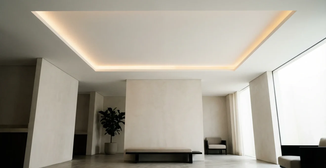
By introducing a shadow gap lighting detail at the transition between the main ceiling and the lower bulkhead, you visually separate the heavy structural element from the rest of the room. The light washing upwards or across the ceiling plane deceives the eye, making the dropped area feel lighter and less intrusive. It transforms a compromise into a tiered architectural feature.
The detail below illustrates how light can be used to soften the transition between differing ceiling heights.
This technique is particularly effective in open-plan spaces where a removed wall has left a beam crossing the room. Rather than trying to hide it and failing, highlighting the transition with a shadow gap creates a zoning effect that feels intentional.
Before any lighting detail can be installed, the structural shell must be prepared, often involving significant alterations.
Key Takeaways
- Reinforce sub-frames with noggins to prevent vibration cracks.
- Adhere to a 1:1 depth-to-pitch ratio or use COB tape to eliminate dotting.
- Install profiles during the boarding phase and protect them from plaster.
Removing Load-Bearing Walls: Costs and Regulations in the UK
Removing load-bearing walls in the UK is a strictly regulated process that typically costs between £1,800 and £7,500, depending on the span and complexity of the steelwork required. This is the prerequisite step for creating the open-plan canvases that minimalist lighting demands. It is not a DIY task; it requires a structural engineer to calculate the beam size and Building Control approval to sign off on the safety of the work.
The cost varies significantly by region and complexity. For a standard kitchen wall removal, you should be budgeting for a £1,800 to £7,500 typical total cost, which includes the steel beam (RSJ), waste removal, and plastering. However, this does not always cover the electrical relocation or the high-end finishing required for shadow gaps.
Regulatory compliance is just as critical as the physical work. You must submit a Building Notice or Full Plans application before starting. If the wall is a party wall (shared with a neighbor), you are legally required to serve a Party Wall Notice up to two months in advance. Ignoring these steps can halt your project and make the property unsellable in the future.
Achieving a flawless shadow gap is a masterclass in sequence and patience. By respecting the thermal properties of materials and integrating the lighting hardware at the correct construction stage, you elevate a renovation from standard to architectural. Consult with your structural engineer and lighting designer early to ensure these details are built-in, not bolted on.